
Disclosure: This post contains affiliate links. If you make a purchase, we may earn a commission at no extra cost to you.
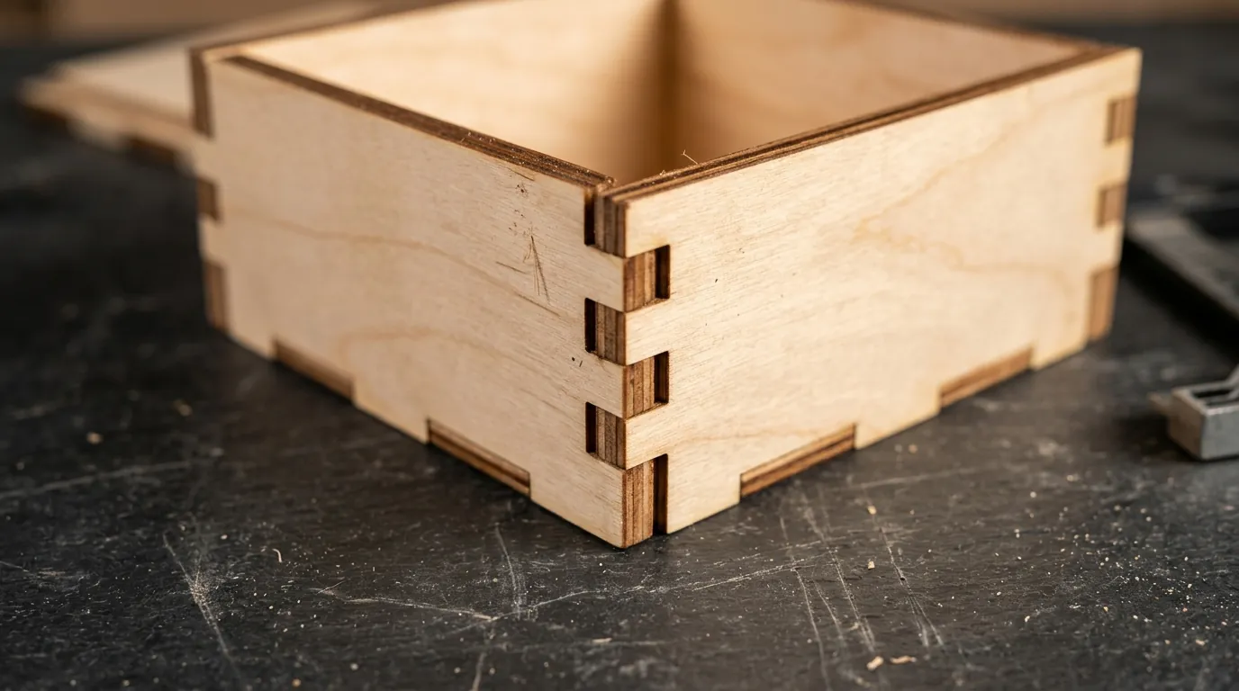
You download a clean box template, load a fresh sheet of 3 mm Baltic birch onto the honeycomb bed, and run the job. Every cut looks sharp. Then you pick up the parts, try to slot the interlocking finger joints together, and face one of two infuriating outcomes.
Either the tabs fall right through the slots with a sloppy, loose rattle, or they refuse to go in by a fraction of a millimeter. When you tap the corner with a rubber mallet, the brittle face veneer splits, ruining four hours of laser time.
Beginners blame their laser focus or assume the digital drawing was flawed. In reality, the issue boils down to basic optical physics: kerf.
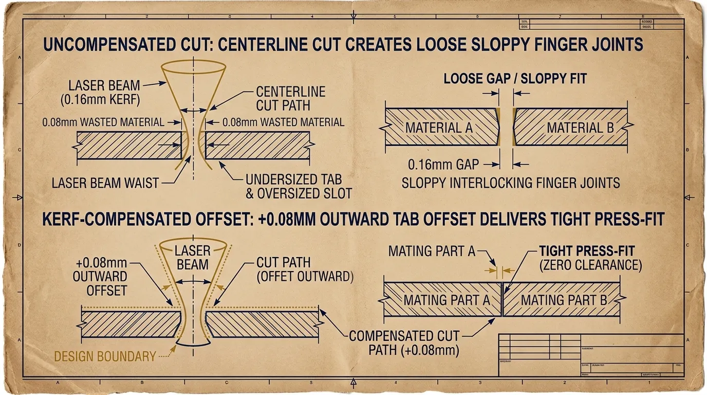
A laser does not cut like an infinitely thin scalpel. It is a focused beam of thermal light that burns, melts, and vaporizes wood fibers. That vaporized trench has a measurable thickness. If your CAD software does not offset the cut paths outward on the tabs and inward on the slots, every outer perimeter ends up smaller than designed, and every hole ends up larger.
Here is a step-by-step method to measure your own laser kerf with a caliper and set kerf offsets in LightBurn, xTool Creative Space and Inkscape for tight press-fit joints.
What Exactly Is Laser Kerf?
Kerf is the total width of material removed by the cutting process. In traditional woodworking, kerf equals the thickness of the circular saw blade (typically 2.4 mm to 3.2 mm). In CNC laser processing, kerf is determined by the optical focal waist of the concentrated laser beam.
Kerf varies with the laser, lens, focus, air assist and material, so there is no single number. The rough ranges below are illustrative only; always measure your own machine:
- Diode Lasers (10W to 20W optical output, 455 nm wavelength): often on the order of 0.1 mm, depending on the lens and focus.
- CO2 Glass Tube Lasers (40W to 80W, 10640 nm wavelength): often somewhat wider than a small diode spot, depending on lens focal length and focus.
- High-Power Diode / Hybrid Lasers (40W+ diode): can be wider because several emitters are combined into one beam.
Because the laser beam cuts along the exact mathematical centerline of a vector line, it removes half of the kerf width from the part you want to keep, and the other half from the surrounding waste skeleton. On a ten-tab box joint, an uncompensated kerf of 0.15 mm (an example value) compounds into about 1.5 mm of cumulative slop across the entire wall seam.
The 10-Line Kerf Measurement Test
Never rely on generic numbers from user forums. Every material batch, lens cleanliness level, and focal distance alters your real beam diameter. Use this standard ten-rectangle calibration test to get your machine’s true kerf in under three minutes.
- Draw the test geometry: Draw ten identical rectangular strips side by side in your software. Make each strip 10.0 mm wide and 40.0 mm tall. Group them into a single outer bounding box.
- Run the cut on target stock: Cut the pattern out of the exact sheet of plywood you plan to use for your boxes. Keep your air assist running at standard cutting pressure (20 to 25 PSI).
- Compress the cut strips: Remove the ten cut strips from the bed. Push all ten strips firmly together against a flat steel rule so there are no air gaps between them.
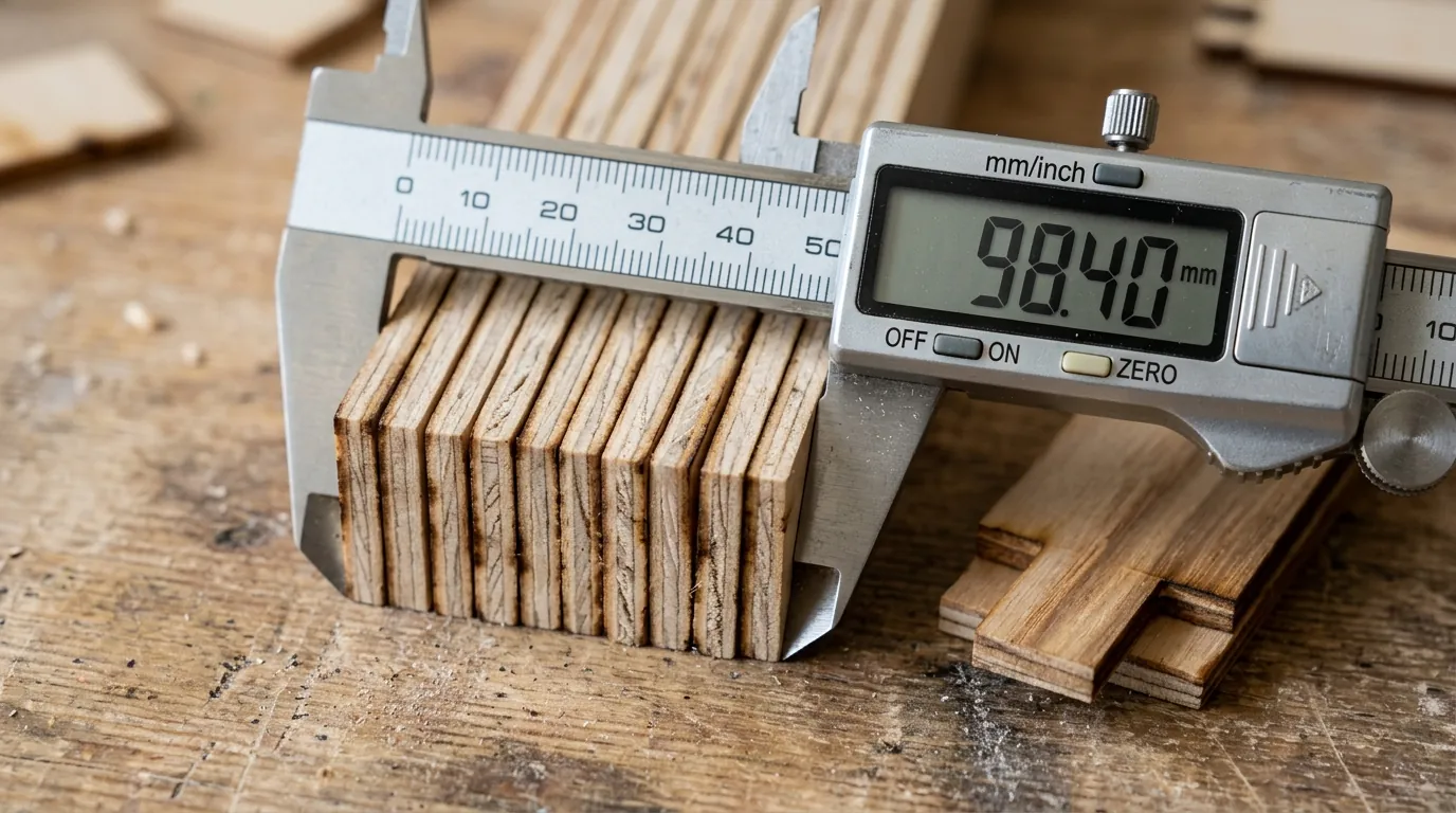
- Measure the total gap: Use a calibrated digital caliper to measure the combined width of all ten compressed strips.
- Calculate your machine kerf: Apply the workshop formula:
Kerf = (Original Target Width – Measured Compressed Width) / Number of Cuts
Example calculation:
- Original width of 10 strips at 10.0 mm = 100.00 mm.
- Measured width of compressed strips = 98.40 mm.
- Number of internal cut lines = 10.
- Calculation:
(100.00 mm - 98.40 mm) / 10 = 0.16 mmkerf.
Your true beam removal width for that specific plywood sheet is exactly 0.16 mm.
Press-Fit vs. Slip-Fit: Choosing Your Joint Tolerance
Once you have your absolute kerf number, you must choose your assembly feel. Plywood is an organic material that swells with room humidity and compresses under pressure.
| Fit Type | Kerf Offset Formula | Assembly Sensation | Best Application |
|---|---|---|---|
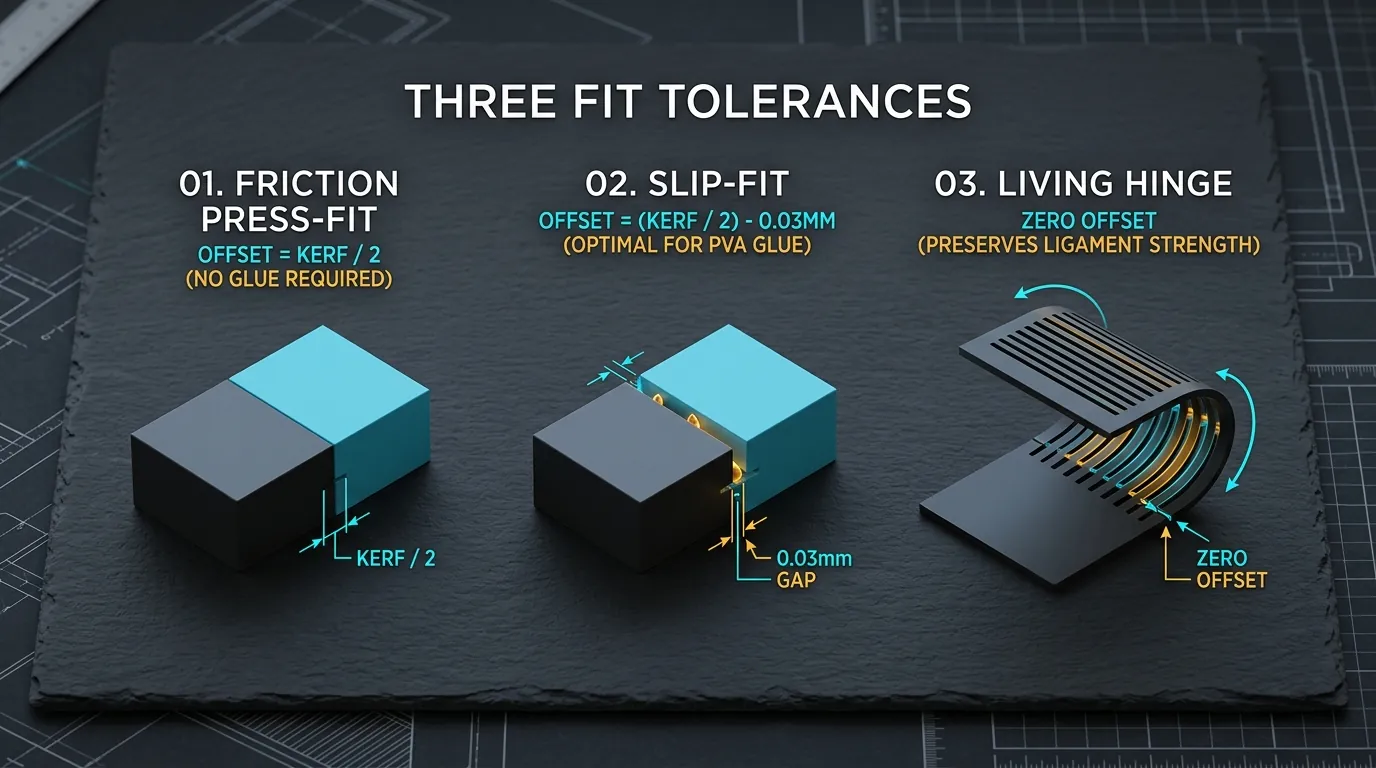
| Friction Press-Fit | Offset = Kerf / 2 (Full Compensation) | Snaps together with firm hand pressure; glue is optional | Display boxes, organizers, decorative shadow boxes |
| Slip-Fit (Glue-Assisted) | Offset = (Kerf / 2) – 0.03 mm | Slides smoothly with micro-gap for PVA glue penetration | Heavy storage crates, tool cases, structural drawers |
| Loose / Hinged Fit | Offset = 0.00 mm (Centerline) | Drop-in clearance; parts move freely | Sliding box lids, rotating gears, living hinge arrays |
How to Apply Kerf Offsets in Popular Software
1. LightBurn (The Cleanest Workflow)
LightBurn features automated kerf calculation built directly into every tool layer:
- Double-click the color layer assigned to your through-cut (for example, Layer 00 Black).
- In the Cut Settings Editor, locate the Kerf Offset input field.
- Enter half of your measured kerf value (e.g.,
0.08 mm). - Choose Direction: Outward for exterior profiles and tabs; Inward for interior holes and mortise cutouts.
- LightBurn computes toolpath displacement on the fly without altering the raw vector geometry.
2. xTool Creative Space (XCS)
In XCS, automated kerf compensation is managed using the Offset vector tool:
- Select your outer box wall panels.
- Click the Offset icon on the top transformation bar.
- Set the offset distance to half your kerf (e.g.,
0.08 mm). - Select Outer Offset for perimeter tabs, or Inner Offset for internal slots.
- Delete or hide the original interior wireframe line, keeping the expanded offset path for cutting.
3. Inkscape (Manual CAD Preparation)
If you design vector templates for sharing or selling on digital marketplaces:
- Open Path → Path Effects → Offset.
- Set your offset distance in millimeters.
- Convert the dynamic effect to raw coordinates via Path → Object to Path before exporting to clean SVG or DXF.
Measuring tip: Measure your plywood thickness in several spots before you set kerf offsets, because sheets vary. A digital caliper is a handy tool for this.

The Nominal Thickness Trap
Even with flawless kerf compensation, your box corners will fail if you overlook material thickness tolerance.
Plywood sold as “3 mm” or “1/8 inch” is almost never 3.00 mm. Due to sanding variations at the mill, a sheet of 3 mm Baltic birch typically measures between 2.75 mm and 3.25 mm.
If your digital vector file has slots designed for 3.00 mm, but your actual sheet measures 3.20 mm, the fingers will stick out 0.2 mm past the face of the box, creating rough, stepped edges. Conversely, if your plywood is 2.80 mm, the tabs will sit recessed below the surface.
Always measure your sheet with digital calipers before opening your design file. Adjust the tab length in your CAD template to match your caliper reading down to the tenth of a millimeter before hitting Start.
Frequently Asked Questions (FAQ)
Does cutting speed affect laser kerf width?
Yes. Slower cutting speeds deliver higher thermal energy per millimeter, vaporizing more wood fiber and creating a wider kerf trench. Higher feed rates with optimized optical wattage minimize heat diffusion and narrow the kerf width.
Should I compensate kerf on living hinges?
No. Living hinges rely on micro-thin wood webs (typically 0.8 mm to 1.2 mm wide). Adding outward kerf offsets thickens the cuts and thins the hinges, causing the flexible wood to fracture under bending stress. Leave living hinge vector strokes uncompensated.
Why do my corner tabs snap when I assemble the box?
Tabs snap when the kerf offset is too aggressive (forcing oversized tabs into undersized slots) or when tabs are cut with their grain oriented across the finger rather than along its length. Always test-cut a 2-tab corner sample from scrap plywood before cutting full-scale enclosures.